Software Countermeasures for Fault Injection Attacks
Abstract
For microcontroller products, the corresponding product specifications are usually set in product planning to restrict the operation conditions of the product and ensure the product can work well.
If the operating conditions exceed the product specifications, it is possible that the system will not function as expected. Such situations are usually used by malicious attackers to seek system vulnerabilities and use the vulnerabilities to bypass the default security mechanism or obtain protected data. This method is usually used by attackers because the related attack device is simple and easy to obtain, low-cost, and its attack works in most microcontroller projects.
In this paper, the common ways of fault injection attacks and their concepts are introduced. Furthermore, the most effective software protection countermeasures against these attacks without increasing hardware costs are mentioned. The countermeasures could provide a simple and effective way to protect the microcontroller production from attack.
What can be done with the Fault Injection Attack – Take hardware crypto engine operation for example
When the execution conditions go beyond the default specification, it will contribute an error operation. If the execution conditions can be controlled to execute in a specific time and only keep a very short period, it will make the MCU go wrong at specific instructions without influencing other instructions. In other words, hackers can use Fault Injection to make specific instructions fail. For example, letting the hardware crypto mistakenly run the task of reading the key and load a blank key (zero key) to encrypt the data. Then the hacker can get the secret data by using the zero key to decrypt the encrypted data.
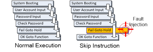
Skip Instruction Attack
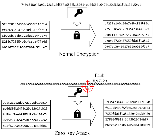
Zero Key Attack
Common and low-cost Fault Injection approaches
Fault-injection attacks can be distinguished as intrusive and non-intrusive attacks.
Intrusive attacks may contribute permanent faults and abnormity to the product's functionality. Intrusive attacks, such as modifying and destroying the product’s internal circuit, usually need highly sophisticated instruments to achieve. Therefore, it requires higher hardware costs and more technical knowledge.
Non-intrusive attacks inject the faults when the product is under execution. Therefore, they only briefly affect a period of operation behavior and results in abnormal or functional failure. Such attacks are usually realized by interfering with the product input voltage and clock frequency.
Because these attacks are directed at voltage and clock frequency in a short duration, it is called voltage glitch and clock glitch. These two attack types can be achieved with equipment that can generate interference with voltage and clock signals, so the cost is much lower and easier to achieve than an intrusive attack.
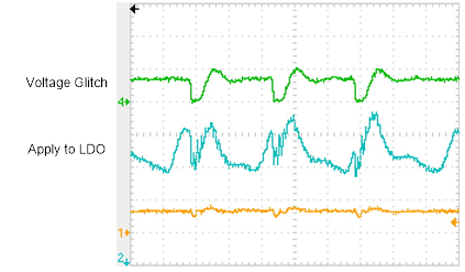
Voltage Glitch Attack
Both Voltage Glitch and Clock Glitch can cause the product to skip certain instructions and affect the output value. The following section will illustrate how the common fault injection impact uses examples of voltage glitch attacks.
Voltage glitch attacks on TrustZone® configuration settings
In microcontroller products with TrustZone® technology, the memory partitions are configured by IDAU (Implementation Defined Attribution Unit) and SAU (Security Attribution Unit). The security attributes could be configured as Secure (S), Non-secure (NS), and Non-secure callable (NSC) by configuring SAU. Their purpose is to protect resources in the secure region by isolating the secure and non-secure region.
To attack TrustZone®, an attacker attempts to break up such an isolation protection mechanism by invalidating the settings of the SAU. This could be achieved by injecting voltage glitch during the system executing SAU configuration, which causes the system to execute SAU setting errors and incorrect SAU configuration. The attacker thinks it could have some exploitable vulnerability with incorrect SAU configuration.
Taking trying to attack the M2351 microcontroller as an example, the entire M2351 Flash memory size is 512KB. If the planning of the secure region size is 256KB, then the remaining 256KB space belongs to non-secure. The memory mapping address is shown below.
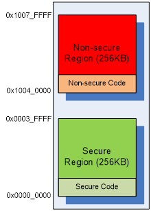
TrustZone® Secure/Non-secure Partition
In this memory configuration, the secure code is separated from the non-secure code by enabling the hardware isolation of TrustZone® technology. To realize the isolation configuration, there are three configuration units required to be set– the configuration setting of SAU, the Non-secure Boundary setting of embedded Flash, and the relative compiler setting.
The SAU could be used to assign a start and end address for the non-secure region. In this example, the non-secure region is set from 0x10040000 to 0x1007FFFF. The other region will be regarded as secure by default. Non-Secure Boundary setting is for setting a partition of embedded Flash for the non-secure region. 0x40000 is set in this case and the system will reserve 256KB for the non-secure region in the second half of the embedded Flash. The Non-secure Boundary is set up before leaving from factory and should not be changed again after deployed.
Because the secure and non-secure regions are separated, they have different RO bases (seeing Figure 4) and it should be considered when building the software. For example, the RO base for security should be located form oxo-ox3FFFF and for non-secure should be 0x10040000-0x1007FFFF. In this case, the secure RO is set based on 0x0 and the non-secure RO is set based on 0x10040000.
Considering the three configuration units above, only SAU settings will be operated when the system is running, so there is a chance to be attacked by voltage glitch. If the attack is launched when settings are written to the SAU, it may cause the instruction to fail and make the SAU's settings incorrect. That is, setting the non-secure region will be failed, causing the actual setting of the SAU non-secure region to be 0x0. This will change the system's memory map as shown in the following figure.
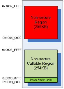
Secure, Non-secure Partition after Attack SAU Setting
Although the non-secure region starting address has tampered, the 0x0 to 0x0003_FFFF memory property is not changed to non-secure. The reason is that the M2351 has another fixed property setting unit which is called Implementation Defined Attribution Unit (IDAU) and it has a higher priority than SAU in the region from 0x0 to 0x0003_FFFF.
In the case of the non-secure region setting from 0x0 to 0x0003_FFFF by SAU, the final properties of 0x0 to 0x0003_FFFF will be defined according to the IDAU. It means that even if a successful attack on SAU and causing the non-secure region starting address set to 0x0, it is still not possible to change the original secure region to a non-secure region. A successful attack on SAU only changes the secure region to a non-secure callable region and the non-secure callable region also belongs to the secure region.
Besides, although a successful attack on the SAU will transform most of the secure region into a non-secure callable region, these regions still cannot be utilized by non-secure code by using non-secure callable function because lacking SG (Secure Gateway) instructions.
The SAU in the M2351 has a total of 8 regions that can be configured. However, the 8 regions are forbidden to be overlapped. These regions configured overlapped will be forced to be secure. That is, if the 0x3F000 to 0x3FFFF has been set as non-secure callable region, it overlaps with the attacked SAU region, 0x0 to 0x107FFFF. It will make the setting of the region from 0x3F000 to 0x3FFFF directly into the secure region and cause all non-secure callable APIs unable to be called by non-secure code.
In short, attacks on SAU settings cannot get additional authority for non-secure code and it even loses the authority for calling the non-secure callable API. Even if a successful attack on SAU settings, it cannot create a valid attack. There will be no disclosure of secure region information or any secure authority obtained by non-secure code.
Voltage glitch attacks on AES
This attack primarily uses voltage glitch to interfere with the operation of AES encryption processing, causing AES encryption to produce incorrect ciphertext. The basic process for performing AES encryption is shown in the following figures.

AES Encrypt Procedure.
For example, the system is attacked by voltage glitch when running AES Key operation, it could cause input key ignored or corrupt the key value. Once the key is not set successfully, the encryption process will use register default value as the key that is usually to be all zero. Therefore, the ciphertext could be decrypted easily by the zero key.

Zero Key Fault Injection Attack
Another situation is that when knowing the plaintext, the attacker can use voltage glitch to generate the wrong key and use it to create encrypted text. Next, according to the results of repeated times, the attacker can use the original text, the encrypted text by correct key, and various encrypted text by error keys to restoring the correct key with the Differential Fault Analysis (DFA) method.
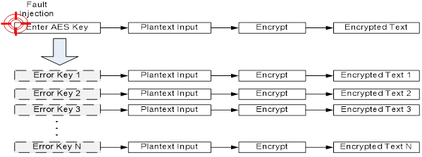
Use Fault Injection to Get N Encrypted Text for DFA
How to protect against these attacks with software
By several examples of voltage glitch attacks above, it can be found that attacker needs to inject fault at a specific time point to skip or interfere system behavior. Therefore, making it impossible for hackers to understand the timing of the inner system working would be an effective countermeasure for a fault injection attack. The simple way is to establish unpredictable system execution timing that makes it difficult for attackers to find the right time point for attack. Unpredictable system timing could also be used to avoid hackers to seek the critical time point of the security operation. For implementing unpredictable system timing, it can be achieved through random delays and random variations in the order of running processes.

Add Random Delay
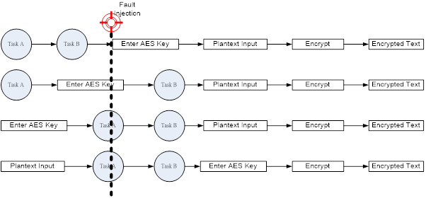
Change Execution Procedure Randomly
However, attackers can still try and error for a long time to seek the specific time point to achieve the purpose of the attack they want. If the software can detect that the system may be under attack, the damage can be minimized by taking action for the attack.
The following section will provide the software solution based on the examples of fault injection mentioned in the previous section, and propose the detection mechanism on whether the system is attacked and the corresponding handling.
Key settings for attack protection
The previous examples of TrustZone® configuration attacks show that attackers attempt to access the secure resources by skipping SAU configuration instructions to influence the secure and non-secure regional settings. The secure and non-secure range settings are related to the SAU but also need to be co-operated with IDAU, so attacking SAU cannot obtain workable permissions to access the secure region. Nevertheless, a corresponding strategy is proposed here for such an attack, so that the attacker cannot even attack the SAU settings successfully.
The primary principle of this protection is to detect abnormal SAU configurations and to restore correct SAU configuration for invalidating the attacks against SAU settings.
The first thing to do is to detect the abnormal SAU settings, which can be checked by redundancy for all SAU settings.
- Record all valid system SAU settings:
System SAU settings are pre-defined within partition_M2351.hthatneeds to be recorded first for use in subsequent steps. - Calculate the sum of valid system SAU settings:
Add up the valid SAU settings such as RBAR, RLAR, and CTRL, etc. for doing the operation will result in a Checksum value. - Write a valid SAU setting to the corresponding SAU:
Write valid SAU settings and attributes within partition_M2351.h to their respective SAU registers. - Readout all the set values are written to the SAU region, and calculate their checksum.
- Check if the SAU settings are correct:
It can be determined whether the SAU settings are correct by checking the checksum value calculated in Step 2 and Step4.
Steps 1, 2, 4, 5 above are the steps to detect an attack and recover the fault, while Step 3 is the original SAU setting procedure, as shown in the figure below.
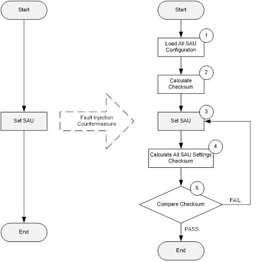
Fault Injection Countermeasure Flow
Next, when the error is detected, the system must be able to recover by itself. The Step3 needs to be repeated to write the correct SAU settings again.
Protection based on Zero Key attacks and AES encryption attacks
Zero Key attacks are similar to the SAU setup attack. They both invalidate the software write action. It makes the system cannot write the correct key to the AES and cause AES to use default key value to encrypt the plain text.
Also, attacks on AES encryptions are designed to corrupt the loading key that generates an incorrect ciphertext. Then, attackers analyze the relationship between several different error ciphertext and correct ciphertext. Then, attackers use the DFA analysis method to derive the encryption key used in the system and then decrypt the ciphertext to get plain text.
To defense AES encryption attacks, the software can detect AES encryption operations to avoid the wrong key or blank key used. The output ciphertext generated by the wrong key also needs to be prevented for DFA analysis.
An attacker needs to point to a specific time before attacking the loading of the key. Because the key configuration is interchangeable with the program of entering the plain text, the software can change them with random order. This makes it more difficult for an attacker to locate the key loading points.

Random change the plaintext, key input procedure
Since the attack on AES operations focuses on making keys being loaded incorrectly, no matter it is Zero Key or a lot of error keys, the software needs to check the key loading in the register at the end to guarantee the correctness. If DMA is used in the operation, the destination and transfer count of DMA should also be included in the check.
For attacks on using keys for encryption operations, by decrypting the ciphertext right after encrypt done with the same key and compare it with the plaintext. In other words, the software can verify whether there are any errors in the encryption process according to the comparison results.
The entire defense countermeasure flow chart is as follows.
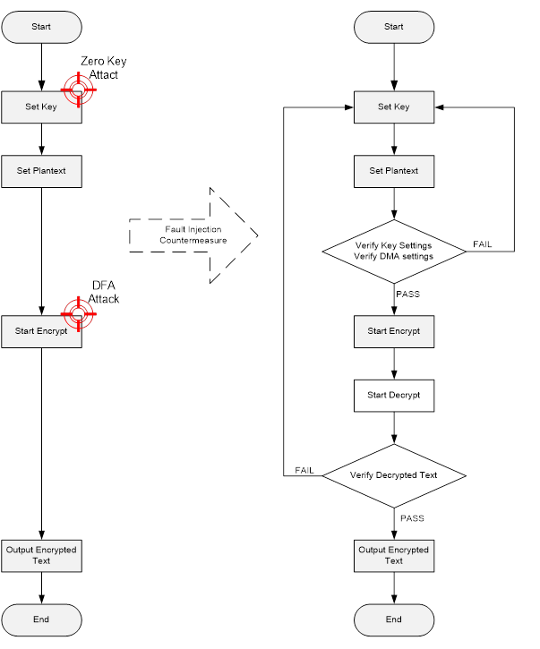
AES Key Fault Injection Countermeasure Flow
Summary
Fault Injection is a simple, effective, and low-cost attack for microcontroller products. To be able to achieve useful results completely, the attack must be able to accurately locate the time point of security settings, key loading, and encryption operations. This is not easy for malicious attacks when the attacker is not familiar with the internal program of the microcontroller. Furthermore, the software can also take advantage of random delay and program staggered to increase the difficulty of locating a specific time point of the program.
Even if an attacker finds a key location precisely, the software can increase the difficulty by adding self-verification procedures to the program. For the important settings in the system and the key loading, adding the corresponding protection will be a worthwhile thing to do.