FAQ
- M051 Base Series(95)
- M0518 Series(97)
- M0519 Series(43)
- M0564 Series(1)
- Mini51 Base Series(90)
- Nano100/102 Base Series(101)
- Nano103 Base Series(10)
- Nano110/112 LCD Series(100)
- Nano120 USB Series(111)
- Nano130 Advanced Series(110)
- NUC029 Series(94)
- NUC100/200 Advanced Series(102)
- NUC120/122/123/220 USB Series(116)
- NUC121/125 Series(1)
- NUC126 USB Series(2)
- NUC130/230 CAN Series(103)
- NUC131/NUC1311 CAN Series(98)
- NUC140/240 Connectivity Series(114)
- M451 Base Series(118)
- M451M Series(117)
- M452 USB Series(130)
- M4521 USB Series(1)
- M453 CAN Series(128)
- M463 CAN FD/USB HS Series(1)
- M467 Ethernet/Crypto Series(1)
- M471 Series(1)
- M479 Motor Control Series(1)
- M481 Base Series(4)
- M482 USB FS OTG Series(4)
- M483 CAN Series(4)
- M484 USB HS OTG Series(4)
- M485 Crypto Series(4)
- M487 Ethernet Series(4)
- M4TK Touch Key Series(25)
- NUC442/472 Series(130)
- NUC472 Series(1)
- NUC505 Series(138)
FAQ
In the M453 series related audio applications, SPI1 or SPI2 are used as I2S function. When I2S is configured to Master or Slave, how do the DI (Data Input) and DO (Data Output) pins connect with an external audio codec device? Issue Date:2018-06-29
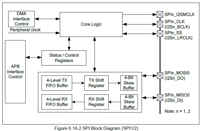
The following figure shows the SPI1 and SPI2 block diagram of the M453 series. The SPI function pins can be Master or Slave.
MOSI (Master Output Slave Input): This pin is the output when the SPI is Master; it is the input when the SPI is the Slave.
MISO (Master Input Slave Output): This pin is the input when the SPI is Master; this pin is the output when the SPI is the Slave.
When SPI1 and SPI2 are used as I²S function, the definition of MOSI and MISO are not applicable. Under the I2S function setting, regardless of whether the I2S is set to I2S Master or Slave, the DI (Data Input) pin is the input of the MISO (I2S_DI) pin, and the DO (Data Output) pin is output from the MOSI (I2S_DO) pin.

| Products: | Microcontrollers ,Arm Cortex-M4 MCUs ,NUC442/472 Series |
|---|---|
| Applications: | Consumer |
| Function: | Peripherals,Connectivity,I2S,SPI |