FAQ
- M051 Base Series(95)
- M0518 Series(97)
- M0519 Series(43)
- M0564 Series(1)
- Mini51 Base Series(90)
- Nano100/102 Base Series(101)
- Nano103 Base Series(10)
- Nano110/112 LCD Series(100)
- Nano120 USB Series(111)
- Nano130 Advanced Series(110)
- NUC029 Series(94)
- NUC100/200 Advanced Series(102)
- NUC120/122/123/220 USB Series(116)
- NUC121/125 Series(1)
- NUC126 USB Series(2)
- NUC130/230 CAN Series(103)
- NUC131/NUC1311 CAN Series(98)
- NUC140/240 Connectivity Series(114)
- M451 Base Series(118)
- M451M Series(117)
- M452 USB Series(130)
- M4521 USB Series(1)
- M453 CAN Series(128)
- M463 CAN FD/USB HS Series(1)
- M467 Ethernet/Crypto Series(1)
- M471 Series(1)
- M479 Motor Control Series(1)
- M481 Base Series(4)
- M482 USB FS OTG Series(4)
- M483 CAN Series(4)
- M484 USB HS OTG Series(4)
- M485 Crypto Series(4)
- M487 Ethernet Series(4)
- M4TK Touch Key Series(25)
- NUC442/472 Series(130)
- NUC472 Series(1)
- NUC505 Series(138)
FAQ
What is the main function of PWM Capture? Issue Date:2015-05-27
PWM Capture and PWM Output share the same hardware. When a rising edge or a falling edge occurs, the value of a PWM counter will be latched into the corresponding rising or falling latch register. At this time, whether to reload the PWM counter or an interrupt event occurs can be determined.
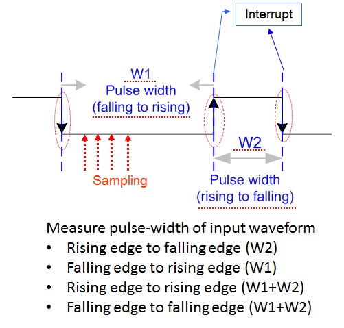
The PWM Capture is mainly used to measure the input waveform of high level and (or) a high-level pulse width. The following diagram is used as example for illustration:

To measure the time W2 from a rising edge to a falling edge (high level), the user can set the PWM counter reload value CN when a rising edge occurs. A falling latch value CFL can be obtained when a falling edge occurs. The time W2 can be calculated using the following formula:
(CN+1-CFL)*(prescale+1)*(clock divider)/PWM_CLK
Note: prescale: 8-bit prescale
clock divider: divider options
PWM_CLK: PWM clock source frequency
| Products: | Microcontrollers ,Arm Cortex-M0 MCUs ,M051 Base Series ,M0518 Series ,M0519 Series ,Mini51 Base Series ,Nano100/102 Base Series ,Nano110/112 LCD Series ,Nano120 USB Series ,Nano130 Advanced Series ,NUC029 Series ,NUC100/200 Advanced Series ,NUC120/122/123/220 USB Series ,NUC130/230 CAN Series ,NUC131/NUC1311 CAN Series ,NUC140/240 Connectivity Series ,Arm Cortex-M4 MCUs ,M451 Base Series ,M451M Series ,M452 USB Series ,M453 CAN Series ,NUC442/472 Series ,NUC505 Series |
|---|---|
| Applications: | |
| Function: | Peripherals,Timer and PWM,PWM-Capture |