常见问答
- M051 系列(95)
- M0518 系列(97)
- M0519 系列(43)
- M0564 系列(1)
- Mini51 系列(90)
- Nano100 / 102 系列(101)
- Nano103 Base 系列(10)
- Nano110 / 112 LCD 系列(100)
- Nano120 USB 系列(111)
- Nano130 USB+LCD 系列(110)
- NUC029 系列(94)
- NUC100 / 200 系列(102)
- NUC120 / 122 / 123 / 220 USB 系列(116)
- NUC121/125 系列(1)
- NUC126 USB 系列(2)
- NUC130 / 230 CAN 系列(103)
- NUC131/NUC1311 CAN 系列(98)
- NUC140 / 240 USB+CAN 系列(114)
- M451 Base 系列(118)
- M451M 系列(117)
- M452 USB 系列(130)
- M4521 USB 系列(1)
- M453 CAN 系列(128)
- M463 CAN FD/USB HS 系列(1)
- M467 Ethernet/Crypto 系列(1)
- M471 系列(1)
- M479 Motor Control Series(1)
- M481 Base 系列(4)
- M482 USB FS OTG 系列(4)
- M483 CAN 系列(4)
- M484 USB HS OTG 系列(4)
- M485 Crypto 系列(4)
- M487 Ethernet 系列(4)
- M4TK 触摸 IC 系列(25)
- NUC442 / 472 系列(130)
- NUC472 Series(1)
- NUC505 系列(138)
FAQ
How to generate an accurate delay time? Issue Date:2020-02-07
If user wants to generate an accurate delay time, it is recommended to use the __nop() to get the accurate one CPU clock cycle delay. However, because the speed of Flash is lower than CPU, some optimization and cache technology will make the __nop() delay not accurate. Hence, it is recommended to put the source code of delay function on SRAM to avoid inaccurate delay time of __nop().
Example: to generate a 2 us delay time accurately.
(1) CPU clock= 32MHz: 1 CPU clock cycle takes 1/32000000 sec = 31.25 ns
(2) 2 us delay time = 2000 ns / 31.25 ns = 64 times of CPU clock cycle
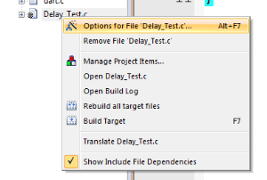
1. Open a new .c file in KEIL project.
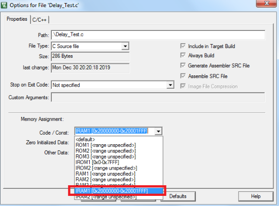
2. Specify the file destination on SRAM.


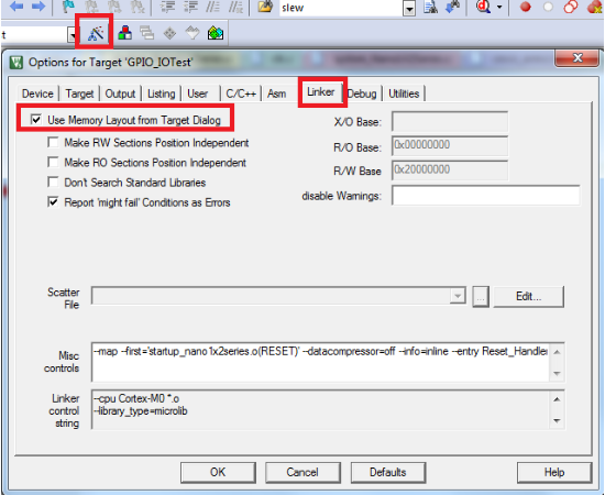
3. Set up Linker.

4. Write the delay function.
Since it takes 5 CPU clock cycles to execute one for loop, user can use the following function code to achieve 2 us delay.
(1) Execute one for loop: 5 CPU clock cycles
(2) Execute one __NOP(): 1 CPU clock cycle
(3) 64 CPU Clock Cycles = 8 ( 5(for loop) + 3 * 1( __NOP() ) )
void Delay_Test_Function(void)
{
for(i = 0; i < 8 ; i++) /* Delay for 2 micro seconds. */
{
__NOP();
__NOP();
__NOP();
}
}
5. Test
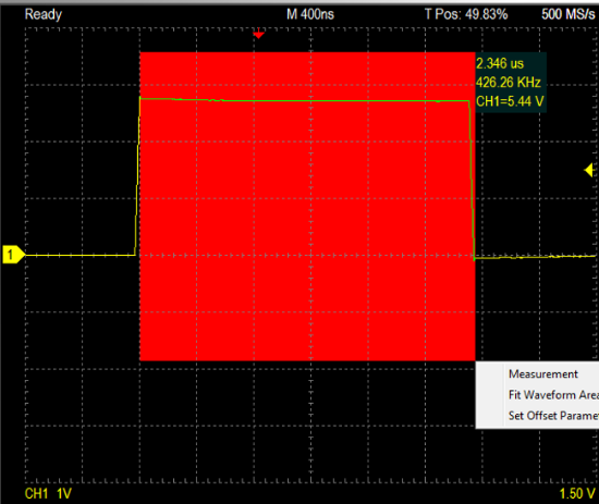
User can take the following function code to test the delay timing. It is recommended to use an oscilloscope to measure the I/O toggle delay time. However, the command executing time (PA0 = 0) needs to be added to the delay time.
Execute one PA = 0: 11 CPU clock cycles
Hence, it will take 64+11 clock cycles. It means that it will take the time:
(64+11) * 31.25 ns = 2343.75 ns.
void Delay_Test_Function(void)
{
uint32_t i, DelayCNTofCPUClock = 8;
PA0 = 1;
for(i = 0; i < DelayCNTofCPUClock ; i++) /* Delay for 2 micro seconds. */
{
__NOP();
__NOP();
__NOP();
}
PA0 = 0;
}

| Products: | Microcontrollers ,8bit 8051 MCUs ,Arm Cortex-M0 MCUs ,Arm Cortex-M23 MCUs ,Arm Cortex-M4 MCUs |
|---|---|
| Applications: | |
| Function: |